

PRESSURE VESSELS
DESIGN OF PRESSURE VESSEL
USING DESIGN BY ANALYSIS (FEA)
Pressure vessels are extremely important to hold elements (semi-solids, liquids, gases) at specific pressure levels. These strategically designed cylindrical closed containers must be built according to exact features and specifications and extreme care should be taken to ensure that there isn’t any kind of loophole in features or construction that can cause leakage and explosion, leading to fatal accidents.
Problem Definition
Design of pressure vessel major dimensions for the given pressure load using ASME codes as well as verification with FEA using MSC Apex.
Solution Methodology
Geometrical specs of the pressure vessel
Thickness calculation according to ASME codes
Finite element verification of the code
Result representation
Finite Element Analysis (FEA) enables pressure vessel designers to study stresses over the entire geometry and optimize material usage. Further, FEA is a tool that helps design engineers to size pressure vessels at much reduced cost and time.
The development in computational technologies has
further permitted designs to be cost-effective for
pressure vessels using the design-by-analysis approach.
Mid-surfacing for the solid model on MSC Apex
As the geometry is considered to be thin walled shell structure, we can use and extract mid-surfaces to use 2-D elements in the solution in order to get better accuracy with less number of elements and fast computational calculations to save time.
Boundary Conditions
In solid mechanics, the general rule for a symmetry displacement condition is that the displacement vector component perpendicular to the plane of symmetry is zero and the rotational vector components parallel to the plane of symmetry are zero.
Material Definition
The ASME SA516 specification is part of the ASME Boiler & Pressure Vessel Code (BPVC) and is a standard which governs the use of carbon steel in weldable industrial boilers and pressure vessels. The following assumptions is made to model the material:
Isotropic and homogenous
No voids and cracks
Analysis is carried out within the yield point of the material
Connections are complete
Load transfer is proper
IN OIL REFINERIES, PVs ARE OFTEN PUSHED TO THEIR DESIGN LIMITS TO MAX PRODUCTION OF GASOLINE AND DIESEL.
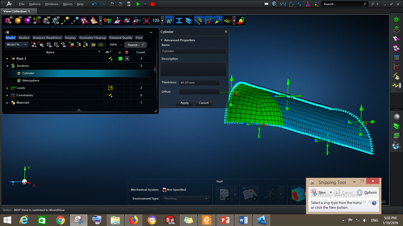
Fig.1 Shell Thickness
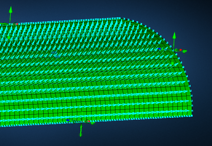
Fig. 2 Internal Pressure Applied
Mesh Attributes
Mesh Type Mixed Quadrilateral and Triangular elements
Mesh Method Auto
Element Type Quadratic Shell elements
Coarse Mesh
Mesh Size = 200.00mm
Number of Elements = 783
Fine Mesh
Mesh Size = 25.00mm
Number of Elements = 49322
RESULTS
The following results shown quite close values to the theoretical values calculated according to ASME code. However, the FEA results are more conservative as it will be demonstrated in the following sections. The maximum stress is 140MPa, which reflects that the design is safe and less than the allowable stresses.
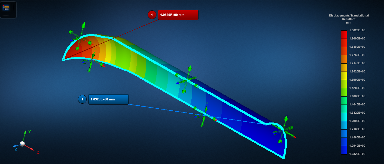
Fig.3 - Translational Displacements indicating max and min values.
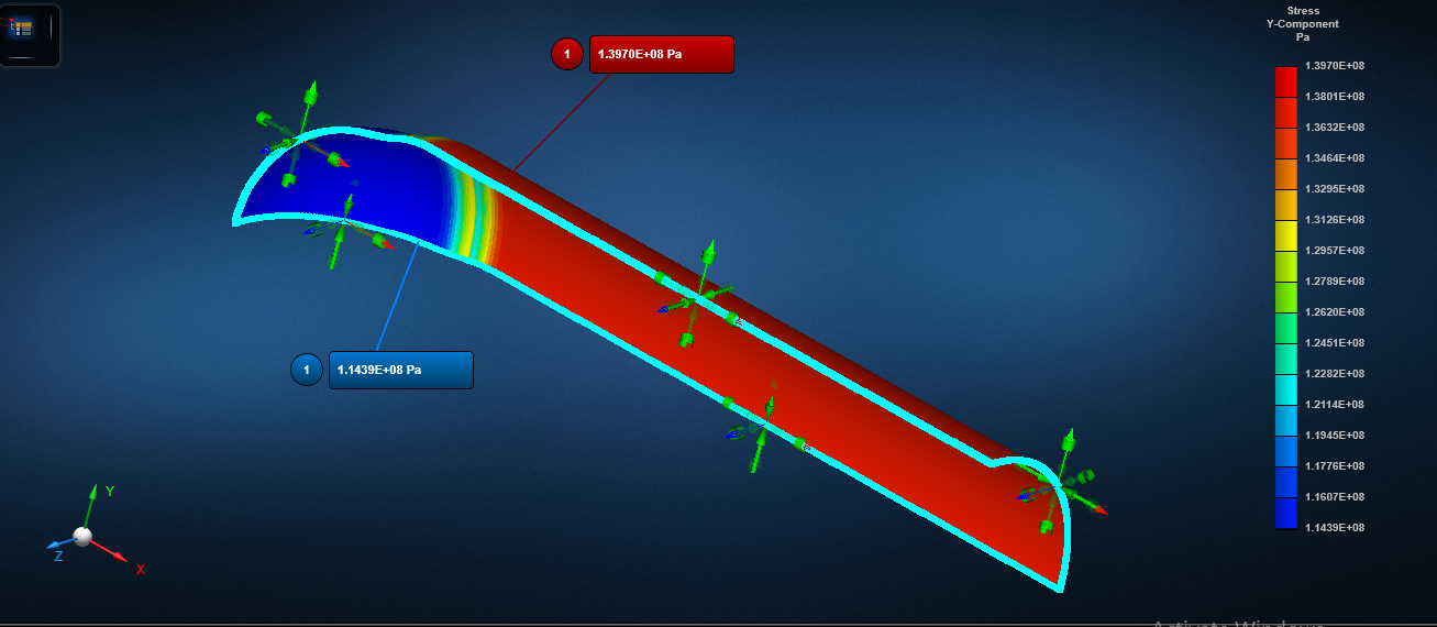
Fig.4 - Hoop Stress Plot for Pressure Vessel.