
WELDING SIMULATION
Welding is the permanent connection of components through application of heat and/or pressure
Welding simulations help in answering:
Do distortions induced by welding influence the final quality of a product?
Do residual stresses have an impact on fatigue properties and/or quasi-static strength of a product?
Are material properties in any way sufficient?
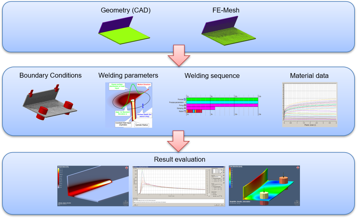
Welding Modeling Workflow
ADVANTAGES
Simufact Welding predicts distortions and residual stresses by virtually try-outs and helps the user to determine appropriate strategies to minimize them.
It automatically considers the complex contact situation between the components, which in turn allows conclusions about the properties of the weld seam, in particular its strength, to be drawn.
Simufact Welding achieves this by calculating the microstructural properties within the heat-affected zone, which also gives the user a valuable insight into identifying welding defects, such as hot cracks in the simulation, and how to avoid them in practice.
Simufact Welding assists in finding the optimal clamping devices based on the implementation of real tool geometries, while considering clamping forces and stiffness.
Besides the clamping concepts, also the suitable welding sequences can be identified. The software predicts the final contour of the assembly and helps to achieve serial production with minimum tolerances. A new visualization concept ensures that the entire welding process, with all its process steps, can be reviewed immediately, influencing factors can be visualized and different variants are comparable at a single glance.
Further welding processes can be simulated with Simufact Welding such as resistance spot welding (RSW), direct energy deposition (DED) as well as dedicated modules for stress relief heat treatment and cooling and clamping processes for the investigation of further subsequent processes after the actual welding process.
Main opportunities to reduce the development cost and time of welded components, are during the:
1) Design of the product, and
2) Planning of welding processes.
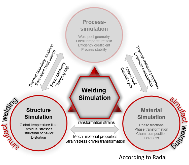
Welding Simulation Sections
Eight reasons why Simufact Welding can innovate your manufacturing:
Identify critical distortions, i.e. with respect to assembly, bulging, imbalances, and clearances
Investigate and optimize clamping tools even before an investment in tools has been made
Identify optimal welding directions and welding sequences
Investigate the influence of unclamping on welding distortions and residual stresses
Gain knowledge about the development of the heat affected zone
Use a tool which supports you during planning of welding processes
Innovate your process design:
Virtually test and evaluate different variables without and
Avoid extremely expensive real tryouts
Examine the material behavior during the welding process
Verify the quality of welding seams, i.e. by calculating nugget sizes, brittle metallurgical phases, hardness, and effects of preheating.
The benefits of simulation welding are best seen in:
Applications Processes:
Arc welding
Laser beam welding
Electron beam welding
Resistance spot welding
Cooling and Clamping
Brazing
Stress Relief Heat Treatment
Real clamp concepts
Fast setup
Best usability
Laser Metal Deposition (LMD) processes is covered by Simufact Welding.
Direct Metal Deposition (DMD)
Directed Energy Deposition (DED)
Laser Cladding
Simufact Welding for Metal Deposition Methods
Analyses the coupled thermal-mechanical response of the process
Investigates the phase transformations during cooling process
Predicts distortions and residual stresses build up during the process
Studies the influence of speed and power of heating sources on the process
Things to learn about a welding process:
Welding sequences
Clamping
Heat sources
Materials
Cooling times
Evaluation of which one is better
Mechanical Boundary conditions:
Fixings
Bearings
Clamping
Local Joints
Weld Path
ROBOT Functions:
Performs the welding process simulation
Defines the weld path
Defines the heat source (geometry and power)
The robot needs the following inputs to work:
Temperature
Material
Trajectory
Welding parameters
Fillet (optional)
These inputs are needed even if the real welding process is done manually.
Welding Parameters
Definition of the energy input:
Transient (indirect power)
Transient (direct power)
Definition of the geometry
Laser (used in beam welding)
Conventional (used in MIG/MAG welding)
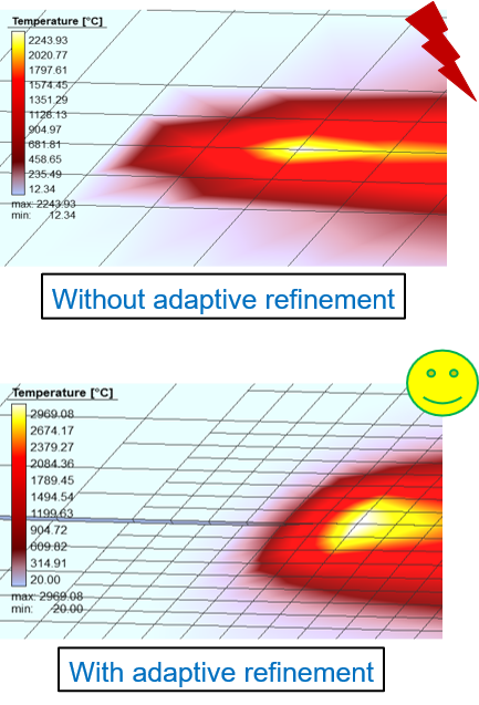
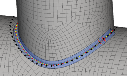
Mesh Density Control
Reach your aim more quickly with process specific functions
Simufact Welding has a modular architecture. The modular concept helps you choose the relevant functions that most exactly fit to your manufacturing processes. Simufact Welding consciously sets apart from competitor’s products by offering deeper process specified functions, rather than following the approach of having ‘general-purpose-tools’ that cover all functions.
The dedicated application modules provide you process specific functionalities for all areas of welding processes. The modules allow for the simulation of single manufacturing steps and can be combined to simulate entire process chains. Additional modules offer you a wide range of further valuable functions for the daily use of the software, such as acceleration of calculations by leveraging multi-core parallelization.
VISUAL RESULTS
Simulation value of different key parameters: distortion, effective stress, in various clamping conditions.
Evaluating EFFECTIVE STRESS for a rear fork cross member welded WITH clamping during weld.
Evaluating CONTACT INTERFERENCE for a rear fork cross member welded WITH clamping during weld.
Evaluating Heat-Affected-Zone for a rear fork cross member using tack weld.
Evaluating Effective Stress for a rear fork cross member welded with tack weld help.
Evaluating Effective Stress for a rear fork cross member welded with tack weld help.