
METAL ADDITIVE MANUFACTURING
Simufact Additive simulates the following applications:
Powder-Bed-Fusion-Processes
Simufact Additive is focused on Powder Bed Fusion processes including Selective Laser Melting (SLM), Direct Metal Laser Sintering (DMLS), LaserCUSING®. The process of Electron Beam Melting (EBM), is mostly covered. [If you’re looking for Direct Energy Deposition (DED) processes, those are currently covered by Simufact Welding]
Using the macroscopic approach, you get simulation results within a few minutes, which predict the tendency of stresses and distortions.
Using the thermomechanical approach, you get the temperature field in addition, which is more accurate but takes longer than the macroscopic approach.
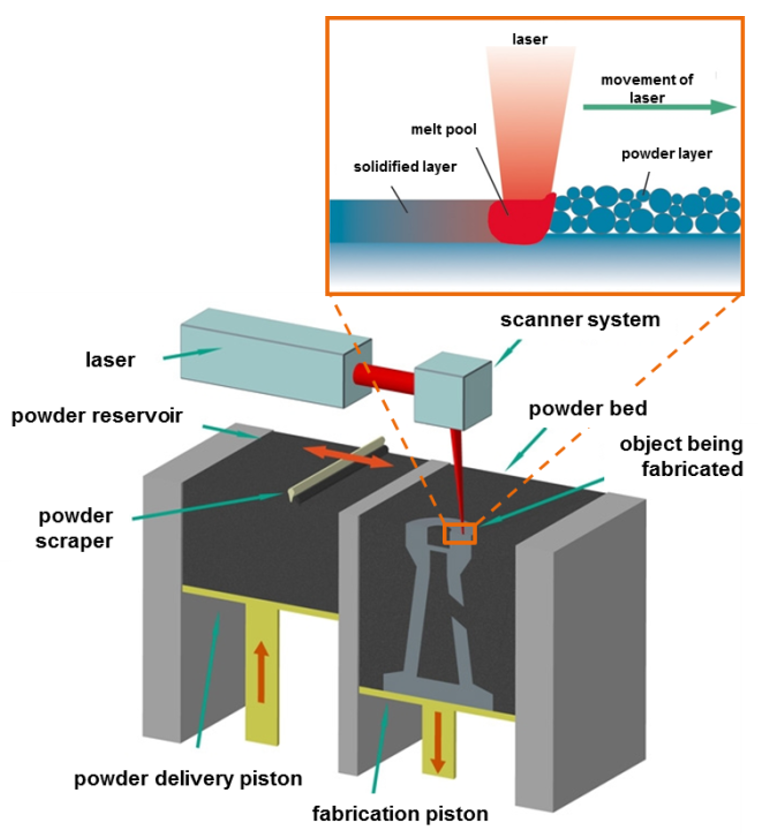
Laser Beam Melting principle with machine scheme (source: Fraunhofer IWU).
Metal Binder Jetting
One of the key challenges for metal binder jetting manufacturers has been to predict changes during the sintering process. As a result, many manufacturers have been unable to realize the potential of metal binder jetting to reduce the time and cost of manufacturing and enable large volume additive manufacturing with metals.
Simufact Additive supports manufacturers to simulate the shrinkage considering i. a. the thermal strain, friction and the gravity during sintering. Compensating these changes, manufactures print 3D parts “first-time-right” and significantly reduce the high proportion of parts which have to be scrapped, re-processed and expensively re-designed.
The required sintering process is a large hurdle that can not be modelled with simple shrinkage models. Our approach considers the thermal strain, shrinkage, friction, gravity, – just to name the most important phenomena during the sintering process.
Using Simufact Additive they can also predict sintering-induced stress in advance, and indicate where defects might occur. Manufacturers can use this information to manually make adjustments and reduce the need for multiple product iterations.
Advantages of Metal Binder Jetting
No supports needed
Many parts can be printed at once with minimal spacing
Suited for larger lot sizes than Powder Bed Fusion
processes
Simulate additive manufacturing - yes;
but to better manufacture or design?
(By Philippe Bauer, A3DM Magazine)
Simulating the manufacture of metal additives makes it possible to better control the manufacture of parts. One of the riskiest phenomena is the tearing off of the tray. Isn’t it too late to find out about this problem when the part arrives at the manufacturing workshop?
In metal additive manufacturing, a certain number of design rules are applicable for each processing method. The most difficult to emit are those concerning the reduction of induced deformations, those due to thermomechanical stresses, created during the transformation of the material. The thermal events that occur during the printing process have serious consequences on the result obtained. Titanium, increasingly used in additive manufacturing processes, for example, increases the number of potential failures. This material imposes high melting temperatures and, in addition, dissipates poorly. It accumulates energies capable of deforming a manufacturing plate. In front of such quantities, one can expect to have to relax one’s tensions provided that the manufacturing cycle has not started with a tearing of the part from its plate... If this is not the case, a relaxation heat treatment “on plate” will allow to release part of the tensions, however leaving residual deformations after dropping. Will these deformations be acceptable? Will it be possible to straighten hot as for a molded part? With an aluminium alloy, why not; with titanium, it is very difficult.
A necessary dialogue
The start of manufacturing requires a dialogue between the designer and the manufacturer. The duration and outcome of this dialogue will be all the more important as the designer has little knowledge of the means of elaboration. The designer’s increase in competence will eventually make it possible to launch a “reputedly manufacturable” part more quickly.
Risk of tearing, deformation, cracking....
In additive manufacturing, the designer must have an idea of the orientation of his part on the plate. Above all, he will try to minimize the height of the print, which determines a significant part of the cost. Coating is time consuming and expensive, especially if the machine is slow to apply. It will also try to minimize the quantity of supports, which are also expensive to remove manually. However, these orientations may be unfavorable to the deformation of the part. Considering that we have a 3D geometry that meets functional requirements and a cost target, it becomes interesting to validate the main lines of a design by simulating its manufacture. The earlier you adapt the design of the part, the less you have to modify it. In such a situation, obtaining deformation trends allows the design to be controlled, if this is done in time.
Software calibration
The software solution is based on generic machine usage models. A “calibration” can be performed so that the simulation better reflects the behavior of the machine / material / parameters association. This involves printing “calibration specimens” delivered by the publisher and measuring their deformations at different stages of the process. These measurements will be imported into the software and will refine its behavioral model. However, these calibrations will only be necessary when exact values are required in order to create a pre-deformed 3D model. For trends, the process can be streamlined. In Figure 1, simple titanium cylindrical tensile specimens fell off the plate. Two thirds of the height of the part was manufactured before the supports tired and ripped off. No one had anticipated this event, but the consequence is, at best, a production stoppage, at worst, a machine that is out of order if the scraper or roller strikes the part being measured. With a little practice, it is possible to prevent this “banana effect”. Before having dedicated software, the experience of “good makers”, in design and manufacturing, may be sufficient to limit the number of manufacturing failures. Because this test piece must make it possible to test a precise printing direction and because its quantity of material is imposed, the only solution is to reinforce the support by adding pylons of full material at the risk of having to make them disappear by machining. It was when the lashing of the straight and full part of the specimen was started that it came off the plate. One rule can be drawn from this: “additive manufacturing does not like to merge endless lengths or continuous surfaces”. If we can, then we must break this continuity.
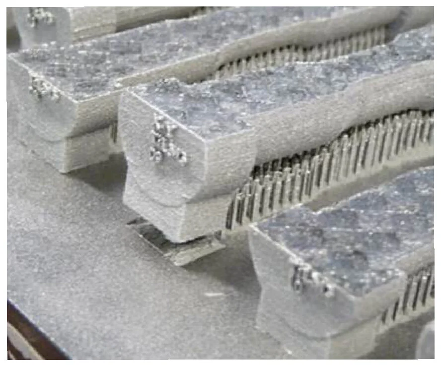
Fig1- Failure to manufacture simple cylindrical tensile specimens.
For more complex cases
Who can predict the problem area(s) on a more complex part? With the right tool, a simulation could detect them. Figure 2 represent the simplified version of a part on which the elements of the problem are stored. Since orientation is imposed and no machining resumption accepted, the part will rest on the plate on the yellow surface and supports will be required on the red and green surfaces.
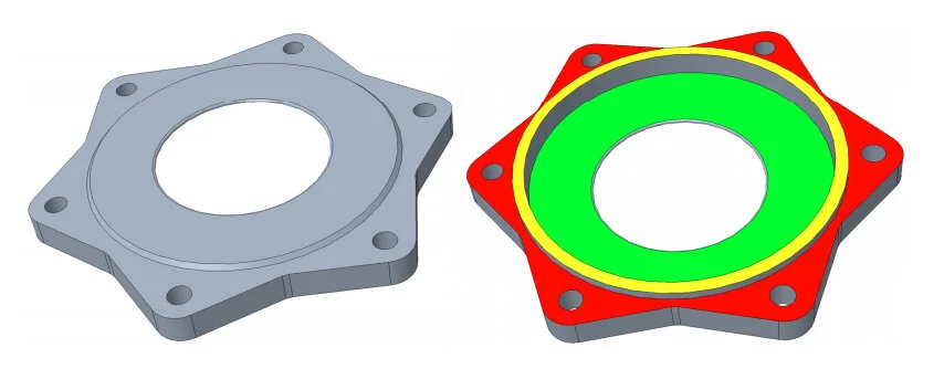
Fig2 - A simple part hiding a difficulty of support
Simulation of the initial part
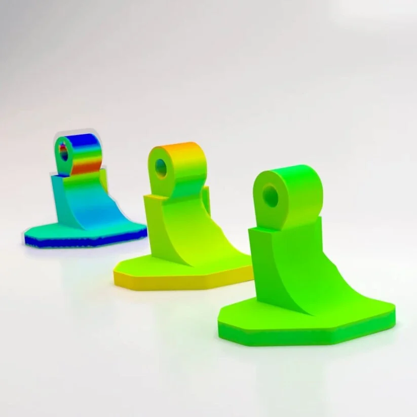
After half an hour of data entry and calculation, Figure 3 shows a very clear maximum displacement zone, locating the proven risk of disengagement at the boundary between the geometry and the support.
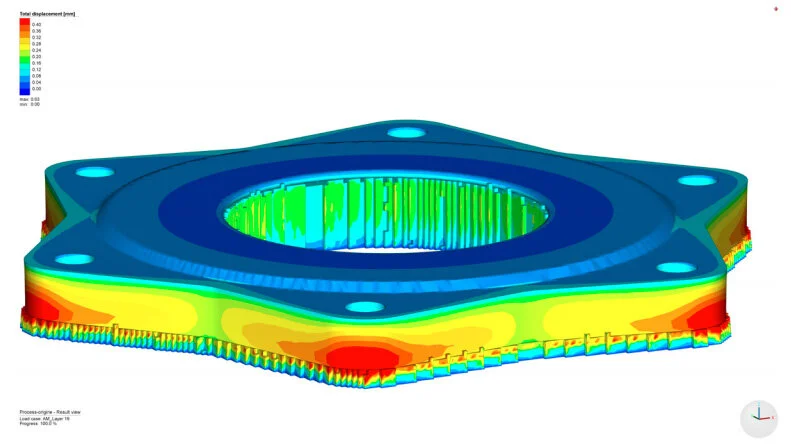
Fig3 - Clear maximum displacement zone
How to solve the problem?
Replacing the supports with rigid and solid material would mean having to redo machining that is not allowed in the scenario. It is possible to reduce the amount of material in the disturbed area by means of a countersinking. But is that enough? In this case, the designer’s participation is required.
In Figure 4, we can see that the risk of pull-out decreases significantly. However, it can be replaced by a risk of cracking on the edges of the lamination.... The best approach will be to limit the material to the strict need by limiting the “fixing function” to very localized bosses. The material saving is in line with the maxim describing topological optimization: “the right amount of material, in the right place and for the right reason”. The questioning of the solution is therefore the responsibility of the designer.
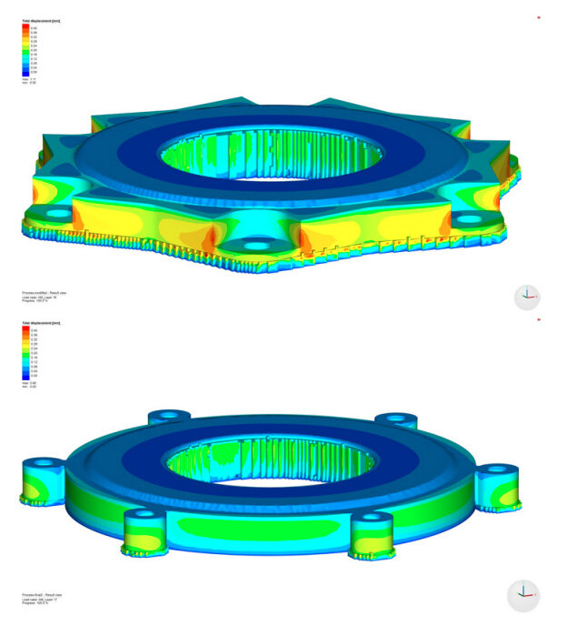
Fig4 - Less material and better distribution prevents the accumulation of local constraints.
An unexpected local failure of support structure
In Figure 5, it is clear that a lifting of the fixing bracket occurred very early in the printing process, interrupting the manufacturing process.

Fig5 - Lifting of the fixing bracket occurred very early during printing.
Simulate at the design office
As long as the behavior of the part can be known in broad terms, the designer can intervene even before the printer takes over. Once the risk of tearing off has been removed, attention should be paid to the treatment of persistent deformations after detachment from the plate. It will then be time to address the management of pre-deformed parts, but this is another story!