
EXTRUSION PROCESS CHALLENGES OF ALUMINIUM PROFILES
SUMMARY
In this report, a numerical simulation is performed to an aluminum extrusion process to investigate the problems of multiple cavity flat profile dies. It can be seen that trial and error using simulation tool can significantly reduce the cost and energy consumption being using in the traditional trial and error. Also, it gives a better insights to each state of the process to efficiently monitor and assess the defects and remedies of the product with drastic return of investment.
Optimization of Controlling Parameters
Optimizing all the controlling parameters of the extrusion process requires a lot of iterations on the production line which costs a lot of labor man-hours along with the energy consumption and scrap rate.
In the present work, a transient numerical simulation was conducted to investigate the complex interaction of different extrusion parameters of the extrusion process such as ram speed, billet, container, and die initial temperatures on the output section required by the customer in terms of exist speed, dimensional tolerances and the tools wear.
In fact, the exact nature of the relationships between design factors and required output required is often unknown. Therefore, simufact.forming is being used to assist in designing and evaluating the performance of the die arrangement during the specified extrusion conditions and provides a good indication on how the die should be corrected. In addition, other parameters can be tuned in order to save bulk of energy consumption, die corrections and material scrape waste to avoid a lot of reworking.
INTRODUCTION
Aluminum extrusion is a complicated process with a lot of interfering parameters. Extrusion dies can be classified into different groups based on the type of the output section required as illustrated in figure [1]. Between the feeder die and the output die the controlling parameters overlie the quality of the extruded profile and this is the complexity of the problem.
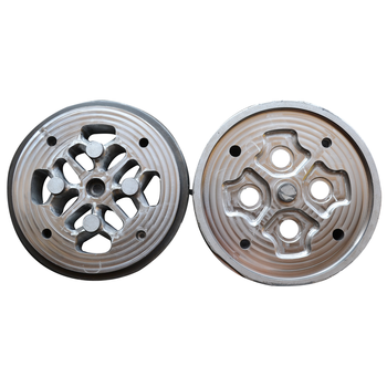
Fig 1: Extrusion Dies with multiple cavities.
CONTROLLING PARAMETERS
Performing iterations with the listed controlling parameters on a simulation software will certainly save huge losses resulting from the physical trial and error technique in the factory workshop.
Effect of Uniformity
The more uniformity is low, the more surface quality will be affected. Stronger corrective measures usually lead to greater overall flow resistance of the dies, limiting the maximum attainable extrusion speed and potentially the lifetime of the die.
Effect of Die Geometry
The die geometry affects the aluminum deformation and how much resistance it will encounter. The container wall friction affects the aluminum flow, and therefore the non-uniformity of the aluminum flow towards the die.
Initial and Reheat Temperature
The die, billet, and container initial temperatures affect the extrusion speed. In addition, low temperatures require more pressure from the press and causes failure to the dies.
Aluminum Composition
The aluminum alloy composition will greatly affect the flow uniformity.
Ram Speed
The ram speed affects the flow non-uniformity and affects the heat generated in the bearing area, and therefore affects the surface quality and die lifetime.
Die Deflection
Due to excessive load on the die during controlling the flow of aluminum, the die may be exposed to deflection during extrusion which may negatively influence the output profile and non-uniformity of the flow.
Die and Billet Properties
Another major complexity to the process is the strain rate, temperature, and pressure dependencies of the material properties of both the aluminum and the die.
Manufacturing Inaccuracies
The die geometry may differ from what the designer intends due to manufacturing inaccuracies, and this may be due to inaccuracies in machines, operator and set-up errors, or even misinterpretation of the design drawings.
CASE DESCRIPTION
The technical case is to be investigated using MSC Simufact forming for preprocessing, solving, and post processing. Simufact forming typically uses two different solver to order to solve the governing equations of the manufacturing problems; Finite Element Solver and Finite Volume Solver. Both are based on numerical discretization of the governing equations. However, for such application, Finite Volume Solver is to be used as it shows great applicability to model the plastic metal flow during the forming process.
In principle, both solutions methods can be applied to any of the forming operations, however, the different treatment of the material deformation has an impact on the applicability. The fact that the FV-elements do not deform with the material, makes the Finite Volume method extremely efficient and accurate when applied to 3D hot extrusion, involving complex material flow.
DIE GEOMETRY
A flat profile extrusion process is to be simulated according to the geometrical and operating conditions utilized by the extrusion company. The die geometry and arrangement are shown in figure [2]:
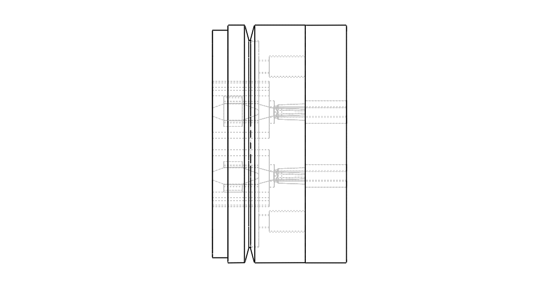
Figure 2a: Flat profile extrusion die side arrangement
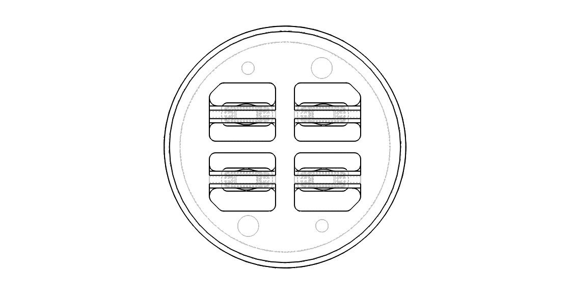
Figure 2b: Flat profile extrusion die front arrangement
EXTRUSION CONDITIONS
For the aforementioned geometry, the extrusion process will take place for the following material and operating conditions:
MATERIAL = ALUMINUM ALLOY 6063
BILLET INITIAL TEMPERATURE = 470 DEGREE CELSIUS
DIE INITIAL TEMPERATURE = 400 DEGREE CELSIUS
CONTAINER INITIAL TEMPERATURE = 400 DEGREE CELSIUS
AMBIENT TEMPERATURE = 50 DEGREE CELSIUS
FRICTION CONDITION = ALUMINUM HOT GOOD
PRESS SPEED = 4.0 MM/S
STROKE = 55.0 MM
MESH SIZING
In order to do a numerical simulation, the billet or workpiece domain has to be broken into pieces, each piece represents an element. A proper sizing of the mesh and type of element would significantly affect the obtained results. For the current simulation, a tetrahedral meshing of element size of 3.0 mm is to be applied to the aluminum billet, and finite volume element size of 4.0 mm is to be applied to finite volume domain that includes the workpiece inside it as shown in figure [3]:
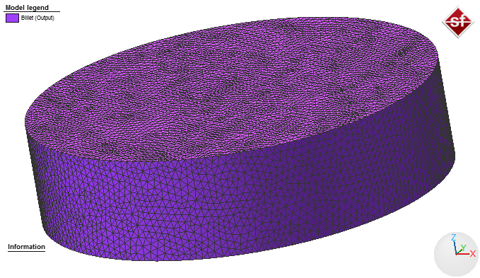
Fig 3a: Billet meshing using Simufact Forming
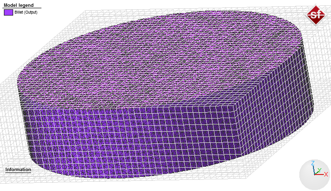
Fig 3b: Billet with Volume Meshing using Simufact Forming
After doing the meshing step, the model to be used for analysis can be seen in figure [4]:
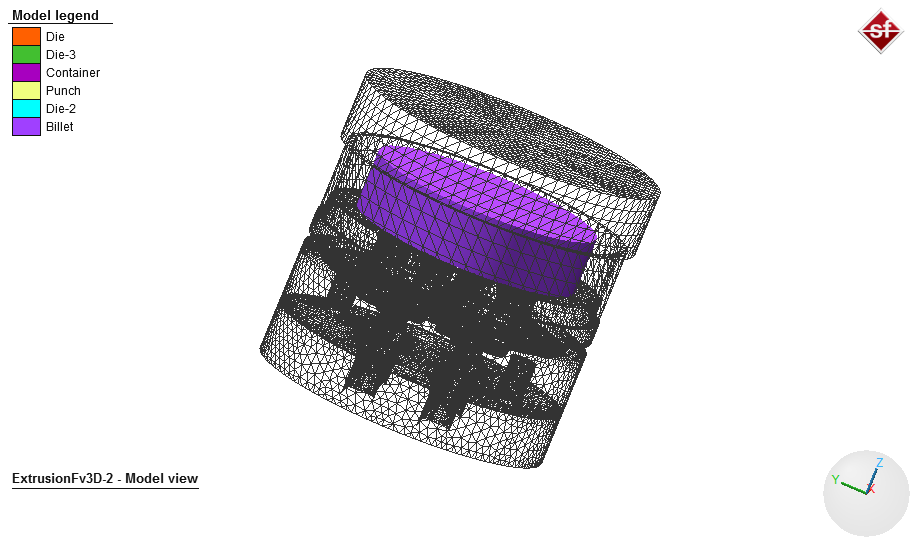
Fig 4: Extrusion model using Simufact Forming
RESULTS
Since the die geometry, and boundary conditions are both symmetrical, it was expected that the flow out of third die would be the same as well. However, since the upper die has multiple of cavities that have different areas, this would greatly affect the flow out of it. The reason why this will happen, as indicated in figure [5], is that the area referred as 1 is wider than 2 which provides a lower resistance to the flow than the narrower one. Thus, the flow of aluminum in area 1 is faster than the flow in area 2 which illustrates the length differences out of the upper die due to speed differences as indicated in figure [6], as well.
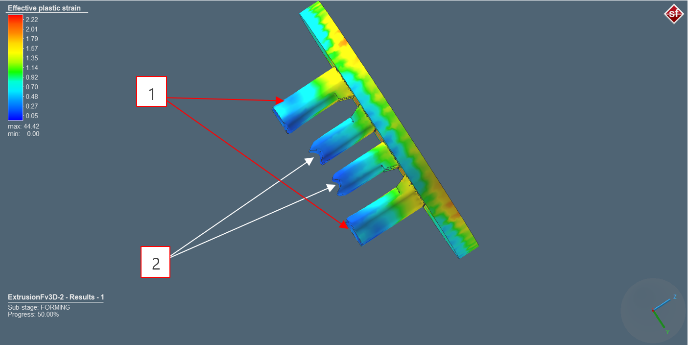
Fig 5: Effective plastic strain out from upper die in aluminum extrusion
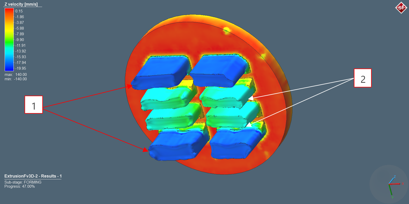
Fig 6: Material flow velocity out from upper die cavities in aluminum extrusion process

Fig 7: Strain rate of material out of upper die in aluminum extrusion process
The differences in speed out of 1 and 2 due to different flow resistance makes the material experiences different stresses and strain rates which drastically affect the deformation of the material out of the process as indicated in figure [7]. Furthermore, since the material out of 1 will reach faster and be in contact earlier with the intermediate die than the ones out of 2, this will let the material out of 1 experience additional compression forces and stresses trying to reach the common cavity between 1 and 2 in the intermediate die. This, of course, leads to different stress distribution across the material cross section due to the aforementioned accumulated residual stresses, which in turn affects the uniformity of the product out the die arrangement as shown in figure [8].
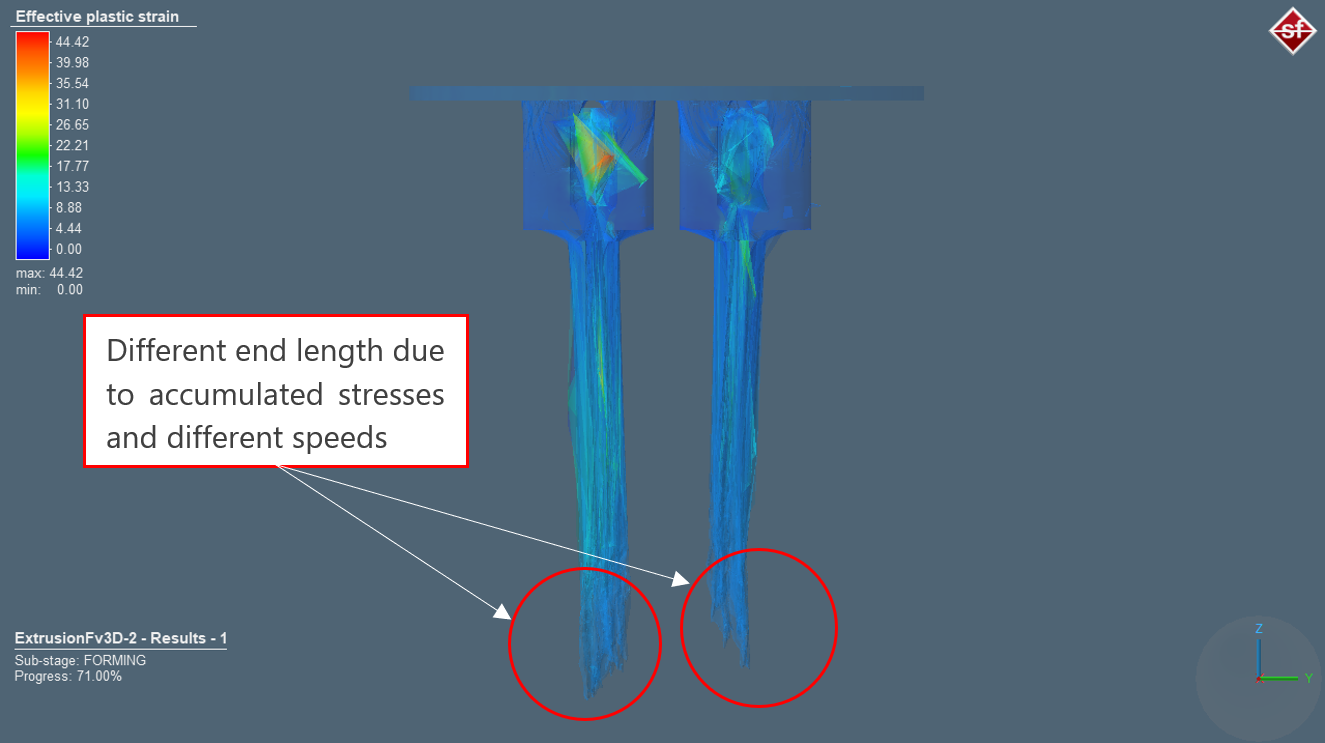
Fig 8: Output defects in extrusion process due to accumulated stresses
BENEFITS OF NUMERICAL SIMULATION
In aluminum extrusion the margin is low and the competition between extrusion companies is fierce. The profit can be increase by increasing the productivity and recovery as mentioned in [6]. Therefore, the traditional way of designing the extrusion dies by trial and error is not only expensive and time consuming but also affects the efficiency of the extrusion process. Typically, the service life of the die tooling components, due to repeated thermo-mechanical loading of the extrusion process dramatically affects the productivity, cost and quality of the products.
For instance, the service life is dependent on wear which affects the dimensional accuracy of the extruded product, and plastic deformation which causes the die components to fail due to fatigue [7]. It was found that 70% of die replacements are due to wear in the hot aluminum extrusion process. Therefore, to achieve cost effectiveness and production feasibility, it is important to predict the wear of the die arrangements at the early stage of product development. Currently in the extrusion industry, development in die design is only dependent on the die designers experience, personal judgment and intuition and trial and error which does not comply with the modern industrial environment of high productivity, lower cost, and lower scrape rate as it cause severe consumption of both time and money.
Traditionally, to reach the desired process parameters through a trial and error and optimal velocity distribution would require up to more than $6,000 per die and takes weeks and month. Using the simulation can take only few hours with total savings of $5000 which is more than 83% of the total cost assigned by the traditional way. For a mid-size company, that produce around 50 new dies per year, annual savings could potentially exceeds quarter-million dollars which is a huge return of investment.
Simufact is an effective tool that helps the manufacturer to design and optimize the process parameters such as ram speed, initial billet temperature, initial tooling temperature, bearing length to ensure the balanced material flow, assess and calculated the die wear and tooling loads and stresses in order to eliminate the product defects and reduce the production costs by reducing the trial and error by 80% of the traditional way. In addition, it provides a visual aid and understanding on how die geometry affects the metal flow and die stresses for quite complex shapes and aluminum profiles.