

PROCESS PIPING
CRACK PROPAGATION IN A PIPE
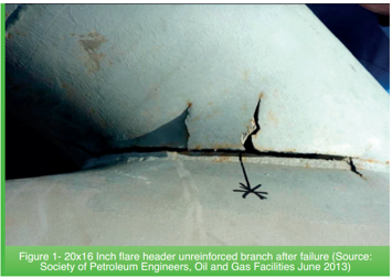
A wall through crack is considered a final failure and the damaged part is no longer fit for service. However, a temporary repair will need to be carried out with clamping and sealing material because isolating this line for permanent repair would mean shutting down the whole train assembly.
Problem Definition
Operations reported that process stream (hydrocarbon) was coming out from the 19” elbow. Inspection was carried out for that leak area after the removal of insulation. A crack of 10mm was observed at the toe of longitudinal weld of original elbow alongside the radius. There was no other reduction of thickness observed in the rest of the part.
Solution Methodology
Geometry creation/import from CAD
Analysis Chaining
Thermal Analysis: Temperature Distribution
Mechanical Analysis: Pressure + Crack Propagation
GEOMERTY
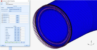
A small part of the pipe has been taken into account. Boundary conditions may differ if the rest of the pipe and clamping strategy is taken into account.
Meshing of the surfaces to perform a 2D representation analysis.
Thickness properties assignment and material properties definition.
THERMAL ANALYSIS
Boundary conditions:
Radial displacement is allowed.
Temperature of 430ºC is applied to the entire pipe
MECHANICAL ANALYSIS
Boundary conditions:
Radial displacement is allowed.
Temperature distribution is loaded from previous thermal analysis.
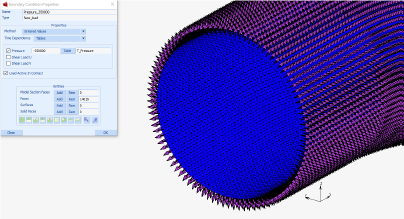
Internal Pressure is applied progressively.
Crack initiator and propagation properties are defined
Two element edges used as mesh splitting crack initiator
RESULTS
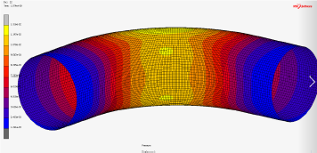
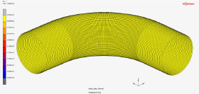
Displacement by temperature increase
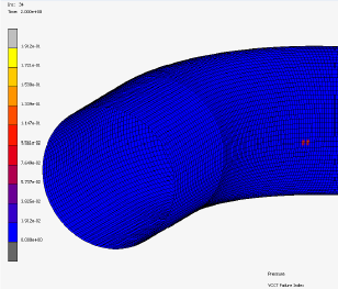
Crack Growth Direction
Displacements results show that the deformation of the pipe is mainly caused by the temperature increase, when operating conditions is achieved and pressure is applied the deformation is the order of 2-3 order of magnitudes less.
Crack is introduced at the second step, at the beginning of the pressure increase. As can be seen there is no propagation of the crack while the pressure increase. If VCCT Failure index reach a value above 1. the crack will propagate. Max value = 0.19