

DRILLING
What is Drilling?
It is a process where the mineral resources are extracted from the earth. These mineral resources could be natural gas, coalbeds, and oil beds. These minerals and natural resources have been formed and entombed at different layers of earth’s crust, at thousands of miles, after being exposed to high levels of pressure and temperature and low supply of oxygen over millions of years.
Drilling Process
Let’s discuss the drilling process. An oil or gas well to be ordered, should follow certain sequence or procedure to get the most benefit of the well and decrease any damages or losses or any environmental pollution as possible. This sequence is nearly applied to any well drilling universally.
1) Well Plan
Exploration well prospects are generated by exploration geologists, while the development of well’s location and objectives are generated by development geologists. Once the surface locations and well objectives are known, the geologists work with the drilling engineers to develop the detail drilling action plans.
2) Perform Shallow Gas Survey
To ensure there are no shallow gas hazards which may result in a kick or blow out, a shallow gas survey is performed to identify the locations and depths of any potential shallow gas hazards. Preliminary surface locations and well trajectories may be altered from the original well proposal to avoid these shallow gas hazards.
3) Prepare the Wellsite
The site is prepared from many aspects. These preparations involves clearing land for building construction, for use by the rig, road access is carefully planned to and from the well site or well pad, constructing infrastructure for water, water disposal, and electricity, precautions and procedure are taken to prevent ground water or water table contamination, dig reserve pits for cutting storage, and drilling the holes which will eventually become the rat hole. The site preparation may involve multiple contractors and companies to perform many required work.
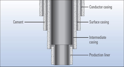
4) Set the Conductor Casing
Prior to the arrival of the drilling rig, an Auger Unit (a drilling machine with a rotating helical screw blade in hard rock regions) will drill a large diameter hole capable of accommodating 18 in. to 36 in. conductor casing. In soft rock regions or at offshore locations, a diesel hammer may be used to hammer the conductor casing into place. The conduct casing may go to depths of 40 to 300 ft. The conductor casing is typically set through the top soil and loose rocks to the bed rock. The objective of the conductor casing is to isolate the wellbore from the top soil to ensure that loose debris does not enter the well during early drilling operations. The conductor casing is then cemented into place.
5) Move-In and Rig Up (MIRU)
Once the wellsite is prepared and the conductor casing is in-place, the rig is brought on location. Most land rigs are transported on multiple trucks. Once the well site is prepared, the rigging-up process begins. Rigging up the well consists of taking the rig modules from the trucks and assembling the rig. Included in the rigging up process is setting-up all of the rig systems and testing these systems.
6) Spud the Well
After the rig has been inspected and all of the systems tested, the well can be spudded. Spudding a Well refers to starting the rotary drilling operations for that well.
7) Drill Down to the Surface Casing Depth
The first section of the well to be drilled is the section that goes down to the pre-determined surface casing depth (Casing Point). Obviously, for this section of the wellbore, the drill bit diameter must be smaller than the ID (inner diameter) of the conductor casing. In this shallow section of the wellbore, fresh water aquifers exist. As well as, shallow gas hazards may also exit. The objectives of drilling this first section of the well, is to allow the setting and cementing of the surface casing to:
Protect the fresh water aquifers by placing a steel and concrete barrier to isolate the water tables from the well.
Protect the well from the aquifer (cutting of the drilling fluids with fresh water).
Protect the well from shallow gas hazards.
8) Run and Cement the Surface Casing
At this point, the drill pipe is removed and pulled out of the hole (POOH) or the wellbore during the cementation operations. The cement is pumped through the interior of the casing and chased with drilling fluid to displace the cement up into the annular space between the casing string and the wellbore and allow time for the cement to harden.
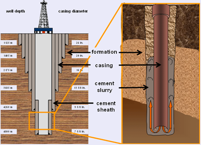
9) Continue to Drill to each Casing Point
This drilling process is continued to the next predetermined casing point. The selection of these intermediate-string casing points is based on the mud weight, the fracture pressure formations, lost circulation zones locations and high pressure zones. Any of these situations may result in a kick and a potential blowout. The objectives of the intermediate casing strings are to isolate these hindrances behind the pipe and prevent the occurrence of blowouts or kicks.
10) Log the Well with Open-Hole Logs
Open-hole logs are used to measure certain properties of the subsurface formation that are of interest to the geologists and engineers working on the well and the reservoir.
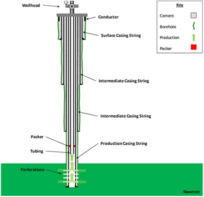
11) Complete the well
Install the rest of well requirements such as tubing, gravel packs, sliding sleeves, packers and artificial lift.
What are Drilling Fluids (Drilling Muds) and their types?
In geotechnical engineering, drilling fluid, also called drilling mud, is used to aid the process of drilling boreholes into the earth. Often used while drilling oil and natural gas wells and on exploration drilling rigs. Drilling fluids are also used for much simpler boreholes, such as water wells. One of the functions of drilling mud is to carry drilling cuttings out of the hole.
The main function of drilling fluids, include providing hydrostatic pressure, is to prevent formation fluids from entering into the well bore, keeping the drill bit cool and clean during drilling, carrying out drill cuttings, and suspending the drill cuttings while drilling is paused and when the drilling assembly is brought in and out of the hole. The drilling fluid used for a particular job which is avoiding formation damage and limiting corrosion.
There are various categories of drilling fluids such as: compressed air, mixed air-water fluid, water-based muds (WBs), which can be dispersed, non-dispersed, non-aqueous muds, usually called oil-based muds (OBs), and gaseous drilling fluid, in which a wide range of gases can be used. Some of the used drilling muds are also used as coolants and provide more control to dust and drilling cuttings.
How the mud is pumped in the wellbore?
On a drilling rig, mud is pumped from the mud pits through the drill string, where it sprays out of nozzles on the drill bit, thus cleaning and cooling the drill bit in the process. The mud then carries the crushed or cut rock ("cuttings") up the annular space ("annulus") between the drill string and the sides of the hole being drilled, up through the surface casing, where it emerges back at the surface. Cuttings are then filtered out with either a shale shaker or the newer shale conveyor technology, and the mud returns to the mud pits. The returning mud can contain natural gases or other flammable materials which may be collected in and around the shale shaker / conveyor area or in other work areas. Because of the risk of a fire or an explosion if they are ignited, special monitoring sensors and explosion-proof certified equipment are commonly installed. The mud is then pumped back down the wellbore and further recirculated. After testing, the mud is treated periodically in the mud pits to ensure and maintain their desired properties and improve drilling efficiency, borehole stability, and other requirements.

DRILLING CHALLENGES
& MSC Simulation Tools Capabilities
Even in a very carefully planned wells, it is almost that problems will occur while drilling a well. Understanding and anticipating drilling problems, understanding their causes, and planning solutions are necessary for overall-well-cost control and for successfully reaching the target zones. These challenges can be: blow-out/kick, stuck pipe, wellbore stability, deterioration of drilling equipment with ROP. Not only these problems that may appear during drilling process but also eccentricity, mud flow, rotation speed, cavitation and vibration issues have strong impact on the performance and the efficiency of drilling process since they waste huge amount of time and money.
MSC Cradle
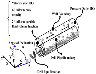
a) The effect of particle shape on the transportation mechanism in well-drilling is investigated using a three-dimensional model that couples computational fluid dynamics (CFD) with the discrete element method (DEM). This numerical method allows us to incorporate the fluid–particle interactions (drag force, contact force, Saffman lift force, Magnus lift force, buoyancy force) using momentum exchange and the non-Newtonian behavior of the fluid.
b) It can be used to simulate the different types of mud flow and lubricants. The changing in phased (liquid to solid) and non-Newtonian field can be considered as well.
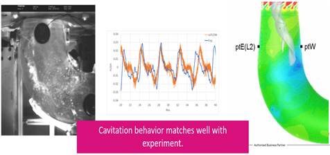
c) Cavitation, shear forces and torque can be calculated and obtained given the right physical properties of lubricant in order to choose the proper cavitation model.
2. MSC Adams Drill
a) It can simulate and model the wellbore path and tortuosity.
b) It has been used specifically to support and simulate the directional and inclined drilling since it has dedicated Rotary Steerable Systems
c) The eccentricity effects to the wellbore can be simulated and capture all sort of dysfunctions.
d) It supports fully coupled, time domain simulations that allows study of transient dynamics and dysfunctions. As well as, vary drill string components, operating parameters, wellbore geometry, lithology and control algorithms are integrated and oriented to understand their effect on drilling dynamics.

e) It is used to predict the susceptibility to erosion for specific pipeline configurations and sand loads using contour maps of erosion rate or relative erosion, particle tracking animations and streamlines.

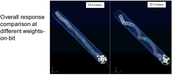
Also a co-simulation between MSC Cradle and Adams Drill can be executed to simulate the pressure and temperature gradient during the drilling process, thus predicting the weight on bit (WOB). In addition to, the localized effects such as flow vortices, back local pressure, mixing drag and turbulence effects can be obtained. However, the multiscale physics should be considered during the modeling stage.

Added Value by Using MSC CAE Tools in Drilling
Primary Effects
Manage Drilling Vibrations
Fewer Failures / Lost In Hole
Reduce Equipment Cost
Reduce Non Productive Time
Increase Average Rate of Penetration (ROP)
More Energy to bit
Increase Rate of Penetration (ROP)
Achieve longer laterals
Secondary Effects
Smoother Wellbore
Improve completions
Produce more per well
Tertiary Effects
Straighter Hole
More Accurate Wellbore Placement
Tighter cone of uncertainty
Produce more per field
REFERENCES
"https://kolonialq.wordpress.com/hydraulic-fracturing-intensive-review/the-process/3-well-injection-part-ii/"
"http://www.bauchemie-tum.de/master-framework/index.php?p=Tief&i=13&m=1&lang=en"
"https://www.slb.com/resource-library/oilfield-review/defining-series/defining-cementing"
"https://www.sciencedirect.com/science/article/pii/S2405656118301329"
"https://www.e-education.psu.edu/png301/node/729"
"https://www.sciencedirect.com/science/article/pii/S0307904X15002917"